
A C14 to C15 power cord is a short equipment jumper used to carry power from an IEC C13 outlet on a PDU or UPS to a device fitted with a compatible C14 or C16 inlet. It is common in server racks, network cabinets, telecommunications systems, and data centers where standardized IEC connections simplify installation and replacement.
The connector combination is only part of the specification. Before ordering, you still need to verify the load, cable construction, temperature conditions, physical fit, required approvals, and the exact interfaces at both ends.
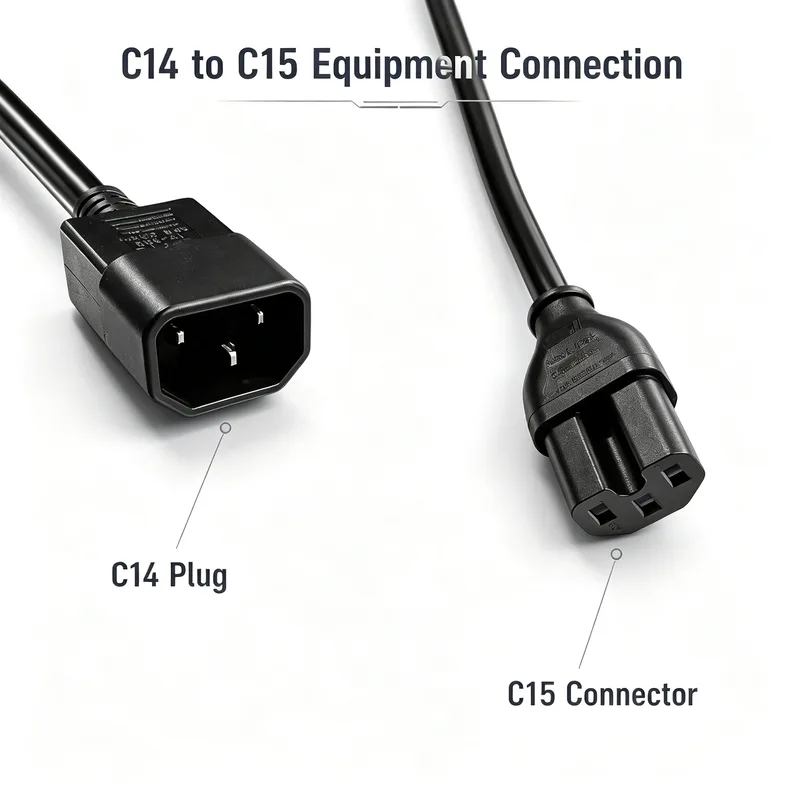
It connects a C13 PDU or UPS outlet to equipment with a compatible C14 or C16 inlet
On the supply end, the male C14 plug inserts into a female C13 receptacle on a rack PDU, UPS, or other power-distribution device. On the equipment end, the female C15 connector mates with a C14 or C16 appliance inlet. That makes the assembly useful as a rack jumper rather than as a wall-plug power cord.
The terminology causes avoidable ordering mistakes. A C14 is the exposed-pin plug or appliance inlet; a C13 is its mating connector or outlet. A C15 is also a female connector, but its keyed shape allows it to mate with a C16 inlet while remaining physically compatible with a C14 inlet. Product photos alone are a poor way to confirm this. Compare IEC interface names and inlet markings.
SEBLIP’s IEC C14 to C15 power cord is specified at 10A 250V and is available with 3×0.75mm² or 3×1.0mm² copper cable.
Why buyers select a C15 connector instead of C13
Buyers generally select C15 when the connected equipment has a C16 inlet or when its operating conditions call for the hot-condition connector family. A standard C13 connector cannot mate with the keyed C16 inlet. The C15 has the required notch, preventing an ordinary C13 cord from being substituted where that interface is specified.
A C15 can also mate with a C14 inlet. Some operators use that compatibility to standardize selected rack cords, but standardization should follow an engineering review rather than connector convenience. C15 assemblies may cost more, and using them everywhere doesn’t correct an undersized conductor, unsuitable jacket, overloaded PDU, or poor airflow.
The C15 design supports hot-condition applications, but connector shape alone does not establish suitability
The IEC C15/C16 interface is intended for hotter appliance conditions than the familiar C13/C14 combination. That distinction concerns the connector system, including the temperature at the appliance inlet pins. It does not automatically qualify the entire cable assembly for every elevated-temperature location.
Check the jacket material, conductor insulation, molded terminations, ambient-temperature rating, approval conditions, and routing. A C15 connector installed on cable with an unsuitable jacket can still harden, soften, crack, or age prematurely near hot exhaust. For equipment with a C16 inlet, obtain the manufacturer’s cord requirements instead of treating “high-temperature C15 power cord” as a complete specification.
A C15 connector does not increase the cord’s current rating or make every high-density rack installation safe
The SEBLIP configuration described here is rated 10A 250V. Fitting a C15 connector does not turn it into a higher-current cord, and a 250V marking does not mean the assembly should automatically be used at 250V in every installation.
Actual use is governed by the cord rating, connected equipment, PDU outlet and bank limits, upstream protection, applicable electrical rules, and any required derating. Dense cable bundles and hot rack aisles can make thermal conditions worse. The lowest applicable rating in the complete power path controls.
Where C14-to-C15 jumper cords fit in PDU, UPS, server-rack, and higher-density infrastructure
A C14-to-C15 jumper cord for PDUs and UPS systems fits several distinct arrangements:
- Rack PDU to server or appliance: The C14 plug connects to a PDU’s C13 outlet, while the C15 connector serves equipment with a C14 or C16 inlet.
- UPS output to network hardware: It can connect a C13 UPS receptacle to compatible switches, storage hardware, telecommunications equipment, or other protected loads.
- Network and telecommunications cabinets: Custom lengths reduce loops of unused cable that can obstruct airflow or complicate service access.
- Higher-density racks: Consistent cord lengths, labeling, and routing help technicians trace feeds, but outlet-bank loading and heat still require separate review.
This cord is not suitable when the source is a wall receptacle, when the PDU has only C19 outlets, or when the equipment requires a C19/C20, regional plug, locking connector, or higher-current connection.
Verify both mating interfaces before treating the cord as compatible
Compatibility means more than having connectors that appear to fit. Confirm the source receptacle, equipment inlet, electrical ratings, keying, installation space, and any retention requirement. Rack equipment is often ordered from several vendors, and a single cabinet may contain C14, C16, and C20 inlets.
Supply side: confirm that the PDU or UPS provides a C13 outlet for the C14 plug
Read the outlet designation on the PDU or UPS data sheet and, where possible, inspect the actual unit. A C14 plug requires a C13 outlet. It will not mate with a C19 outlet or a domestic wall receptacle. Also confirm the outlet’s voltage, current limit, switched or metered status, and bank assignment. A physically open C13 receptacle may still belong to a bank that lacks capacity for the proposed load.
Equipment side: identify the C14 or C16 inlet and check keying, clearance, orientation, and retention
Confirm whether the device has a C14 or keyed C16 inlet. Then look at the space around it. Deep molded connectors, adjacent ports, rack rails, cable-management arms, and sharply angled rear panels can prevent full insertion even when the IEC types match.
Standard IEC connectors generally depend on friction unless a separate retention feature is specified. If accidental disconnection is a concern, ask whether the equipment supports a clip, locking mechanism, or approved retention accessory. Don’t substitute a tight bend or cable tie around the connector for proper strain relief.
Choose the 10A 250V cord configuration by conductor size, length, jacket, load, and installation environment
SEBLIP offers 3×0.75mm² and 3×1.0mm² cable options for this 10A 250V category. The larger conductor can provide more electrical and thermal margin, particularly on longer runs, but it may also produce a thicker, less flexible cable that occupies more routing space. Conductor size alone does not override the cord’s marked 10A rating.
Length should be based on the real routed path, not straight-line distance between outlets. Allow enough slack for servicing and cable-management movement without leaving coils in hot or congested areas. Jacket selection should reflect temperature, flexibility, abrasion, flame-performance requirements, and the documentation demanded for the installation. Confirm these points in the custom-length C14 to C15 power cable specification before approving a production sample.
Use a complete RFQ checklist: 3×0.75mm² or 3×1.0mm² cable, length, jacket, labeling, packaging, quantity, lead time, and applicable US compliance documentation
A useful RFQ gives the factory enough information to quote the same assembly you intend to approve. Include:
- IEC C14 male plug to IEC C15 female connector;
- 10A 250V required rating;
- 3×0.75mm² or 3×1.0mm² copper cable;
- finished cord length and permitted tolerance;
- jacket material, color, and environmental requirements;
- straight or other required connector orientation;
- equipment load and expected installation temperature;
- label text, serial or asset identification, and private-label requirements;
- individual, bundled, or bulk packaging;
- order quantity, sample requirement, and production lead time;
- destination market and the applicable US compliance documents, file references, test reports, or customer approvals required for the finished cord;
- retention, inspection, and electrical-test requirements.
Finish by checking the production drawing against the actual PDU outlet and equipment inlet. That final physical comparison catches the expensive errors: reversed connector assumptions, inadequate clearance, the wrong jacket, and a cord length measured without following the rack’s routing path.